How to Install a Peterbilt 379 Bumper Lift Kit Using 5 Steps
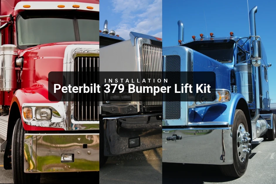
Flip kits protect your expensive custom bumper from getting scraped. Simply flip a switch in your cab and the bumper lifts 8-inches in a few seconds.
If you're looking to install a Peterbilt 379 bumper flip kit for extra ground clearance and maneuverability, here's an expert-led breakdown from 12 Gauge Customs of exactly how to do it.
During an installation, you have to consider: lift arm geometry, air cylinder operation, bumper swing travel, regulator tuning, and proper blind-mount bumper integration.
How Peterbilt 379 Lift Bumpers Actually Work
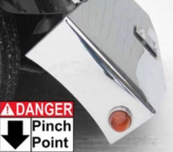
The 12 Ga. Peterbilt 379 bumper lift kit isn't just an air cylinder that raises the bumper, it consists of:
- Lift arm mechanisms
- Pivot points mounted in the factory bumper location
- Air cylinders
- Cylinder ounting brackets
- Blind-mount bumper plates
- Lift plates that carry the bumper weight
Mechanical Sequence

Air pressure is applied to:
- Open the solenoid
- Air enters the cylinders
- Cylinder rod extends
- Lift arm rotates upward
- Lift plate pushes bumper up
- Entire bumper rotates away from hood path

When pressure is released: the cylinder retracts, lift arm rotates down, and bumper returns to normal driving position.
5 Step Flip Kit Installation Workflow (Simplified)
- Remove the Bumper
- Install the Lift Arm
- Secure the Air Cylinder Mounts
- Integrate the Blind-Mount Bumper Backing
- Test and Adjust Lift Kit Activation Using the Cab Toggle Switch
The total installation process can take 8 hours, especially if it's a first-time DIY attempt to wire a flip kit to the pneumatic system.


#1. Remove the Factory Peterbilt Bumper
Goal: Create a clean mounting surface that replaces the factory bumper mounting structure in order to attach the lift-arm assembly.
- Remove the factory bumper from the front frame rails.
- Remove the factory bumper support brackets.
- Reinstall any factory 5/8" frame bolts that were removed during disassembly.
The original bumper has to be removed completely before you install the lift kit.
The lift kit has its own lift arm mechanism that replaces the original bumper supports.
When removing the bumper, you need to remove the rubber radiator shrouds located on the front side of the radiator. These will block your access during installation.
Inspect the frame rails once the bumper and brackets are removed. Make sure there are no bent surfaces, rust, corrosion, or missing hardware pieces.
Reinstall any of the factory 5/8" bolts that you removed with the bumper. They can be reinstalled into the framerails. You'll use these bolts as referential mounting points to help you later on.
What should be done by the end of the first step:
- Removed the factory bumper completely
- Removed (and saved) the support bracket hardware
- Removed the radiator shrouds
- Exposed front frame rails
- Factory frame hardware (5/8" bolts) get reinstalled
- Clean mounting points are now ready for the lift-arm assembly
#2. Lift Arm Assembly Installation
Goal: Square both lift arms so they move together as a single assembly.
What happens:
- Bolt the lift arm mechanisms into the original bumper mounting holes using the factory hardware.
- Leave all mounting bolts finger-tight initially.
- Install the temporary guide plates.
- Set the bumper loosely on the guide plates to ensure both lift arms are perfectly aligned.
- Once alignment is verified, remove the bumper and fully tighten the lift-arm mounting bolts.
The Lift Arm Alignment
Always use guide plates to keep the lift arms parallel to the bumper.
Step 1: Install the lift arms with loose bolts for easy realignment.
Step 2: Use the bumper as an alignment tool.
Step 3: Verify that the lift plate is symmetrical and parallel.
Step 4: Remove guide plates after alignment.
Doing this ensures equidistant bumper travel distance, prevents binding when the flip kit is used, and establishes proper bumper positioning before tightening it in place.
If the lift arms are not square, the bumper can:
- Rise unevenly
- Twist during operation
- Wear down cylinders
- Touch the hood or grille
How to Square the Bumper Lift Kit Assembly
A "squared" Peterbilt 379 bumper flip kit assembly means it is geometrically aligned in these ways:
- Side-to-Side: the bumper protrudes equally from both sides of the truck
- Front-to-Rear: both lift arms align at the same fore/aft positions
- Vertical: lift plates support the bumper at identical heights
- Operational: the bumper smoothly raises and lowers without twisting
Why Guide Plates are Critical During this Phase of the Installation
New lift kit designs come with two guide plates to help align the bumper while the lift kit is being positioned for installation.
These accessories save you from costly mistakes.
For example, let's say that one arm is 1/8" ahead of the other. The bumper will then twist and contort during a lift.
If the lift kit geometry isn't aligned with the bumper, you might see:
- Uneven gap between the bumper and grille
- One side lifts before the other
- One cylinder carries more load
- Premature bushing wear
- Air cylinder side-loading
#3. Air Cylinder Mounting
Goal: Connect the air-powered cylinders that will drive the lift-arm mechanism.
What happens:
- Mount the cylinder brackets to the frame rails.
- Install a 5/8" washer between the frame and bracket as instructed.
- Attach the air cylinders using the supplied clevis pins and hardware.
- Tighten the nylock nuts only enough to secure the cylinders while still allowing free pivot movement.
Cylinder Bracket Positioning
The air cylinder bracket has a unique mounting feature:
- Rear hole clears an existing 5/8" frame bolt head
- Front hole is used for securing bracket
- Washer must be installed between frame and bracket
Incorrect spacing the cylinder brackets could cause issues like:
- Cylinder misalignment
- Binding
- Uneven bumper lift angles
To avoid this, double check your measurements/spacing.
#4. Blind-Mount Bumper Integration
Goal: Permanently connect the blind-mount bumper to the lift-arm assembly.
What happens:
- Place the bumper on the lift plates and guide plates.
- Center and square the bumper on the truck.
- Move Bracket "A" against the bumper's backing plate.
- Mark the required drilling locations.
- Remove the bumper.
- Remove the inner bumper plates.
- Drill:
- Two 1/2" holes
- One 3/8" hole
- Remove the temporary guide plates.
- Bolt the bumper plates to the lift-arm assembly.
- Reinstall the bumper and make final fitment adjustments.
Blind-Mount Compatibility
Unlike standard front bumpers with exposed bolts, blind-mount bumpers have a bumper backing structure that requires some fitting and drilling in order to get the lift kit to fit.
Installation requires:
- Positioning the bumper on lift plates
- Moving Bracket A against the bumper backing plate
- Marking the mount hole locations
- Drilling two 1/2" holes and one 3/8" hole
This will createa a custom mating surface between teh lift assembly and the backing bumper structure.
Drilling Tips for the Blind Mount Bumper Flip Kit
- Transfer mount hold locations
- Ensure proper lift kit geometric alignment
- Maintains the correct bumper orientation
After you market the location from Bracket A, identify the exact drill hole pattern locations.
You'll need to drill two 1/2" holes and one 3/8" hole.
The two small drill holes are the points that carry the bumper weight upon lift. The single 3/8" hole is the anti-rotation point that stabilizes the bumper while in operation.
Remove the inner bumper plates to drill the newly marked holes. It's important.
Drilling through the existing assembled bumper holes will misalign the plate interfaces and put stress on the fasteners.
Removing the bumper plates beforehand will ensure you have accurate drill holes and clean hardware seating.
Once you're done drilling, use the slotted mounting holes on the bumper to adjust the bumper's position until the top of the bumper is flush with the grille or at least 1/16" below the grille.
Check & Adjust the Bumper Height
Once it is installed, use the slots in the bumper plates to adjust the height (ground clearance level).
The top edge of the bumper should sit flush with the grille or 1/16" below the grille.
Verify the Hood Clearance
Before activating the air pressure that controls the lift kit, verify the hood clearance as well:
- Open the hood slowly
- Check the bumper clearance
- Verify if the hood has enough travel room when opening and closing
If it's not spaced properly, you could see failure points when activating the lift kit:
- Surface-level hood damage
- Paint chipping
- Chrome bumper contact to the ground surface
- Excessive lift-arm travel
#5. Pneumatic & Electrical Setup and Adjustment
Goal: Fine-tune the air pressure so the bumper raises smoothly and consistently.
What happens:
- Mount the electric solenoid valve in a protected location (the instructions suggest the battery box).
- Run switched 12-volt power and ground from a customer-supplied dash switch.
- Connect the air lines to the cylinders and solenoid.
- Charge the truck's air system.
- Cycle the solenoid until it operates smoothly.
- Adjust the air regulator.
- Slowly increase pressure until the bumper fully raises.
- Add approximately one-half turn of regulator adjustment after achieving full lift.
- Verify operation.
Pneumatic System Lift Kit Check
The lift kit uses:
- Air regulator
- Solenoid valve
- Dual cylinders
- T-fitting distribution
The configuration includes:
A = Normally Open
B = Normally Closed
P = Air Supply
Adjustment Procedure Explained
Start the any pneumatic/electric lift kit adjustments in this order:
- Charge the air system
- Increase regulator pressure
- Cycle solenoid until smooth operation
- Reduce pressure until supply cuts off
- Slowly reintroduce pressure
- Add 1/2 turn after full bumper lift
This tuning procedure is designed to minimize excess force air, cylinder shock loading, and to prevent janky bumper movement every time you use the bumper lift kit.
Step 1: Charge the Air System
Start the truck and let the air tanks reach normal operating pressure. Since the lift kit uses air to move, you won't know if the issue is an incorrect regulator adjustment or low air pressure.
Step 2: Increase Regulator Pressure
Turn the regulator adjustment knob to let more air into the bumper lift kit system.
You are gradually giving the air cylinders enough pressure to move the bumper. This lets you spot any potential issues with your installation.
Step 3: Cycle the Solenoid Until Operation is Smooth
Operate the bumper switch several times: repeatedly raise and lower it.
This helps do a few important things:
- Fill the air lines
- Remove trapped air
- Verify the wiring connections are unhindered
- Verify the solenoid is working correctly
- Verify the cylinders can move freely
Step 4: Reduce Pressure Until Air Supply Stops
Turn the regulator down, lowering the air pressure, and lowering the bumper.
You'll notice the minimim air pressure point (a baseline) where the lift kit system will no longer work.
Step 5: Slowly Reintroduce Air Pressure
Start increasing the air pressure to the lift kit once more.
This is how you identify the lowest pressure level that will still raise the bumper to its full clearance height.
After each air pressure adjustment, activate the bumper, look at how it moves, and increase pressure if you need it.
Step 6: Add One-Half Turn Beyond Full Lift
Once the bumper effectively reaches full lift height, turn the regulator an additional 1/2 turn.
Doing this will add a small safety margin in case of cold weather, air pressure changes, or system wear over time.
This will give your bumper flip kit enough air to operate consistently while not over-pressurizing the cylinders.
The goal is to adjust the kit to operate at the lowest air pressure that will still efficiently lift the bumper each time you use the flip kit.
If you do it correctly, you should see:
- Bumper lifts smoothly
- Bumper reaches full height
- No jerking or slamming
- Both sides move evenly
- Consistent operation every time switch is activated
Shop Peterbilt 379 Bumper Flip Kits at 4 State Trucks
Get a warranty-backed, premium bumper lift kit assembly for your 379 model year. Shop online, use the mobile app, or stop by our retail store off I44 highway in Joplin, Missouri.
Recent Posts
-
Semi-Truck Mattress Sizes: Fitment Chart & Buying Guide
 Looking for the right sized semi truck mattress? Every long-haul trucker should prioritize spending …29th Oct 2026
-
5 Truck Shows You Don't Want to Miss in 2027
 What are the best truck shows in America? Over the years, we've visited them all at one point or an …22nd Oct 2026
-
Haul of Fame: Chad Smith’s Custom 2019 Peterbilt
 Some trucks are built to work. Some are built to show. Then there are trucks like Chad Smith’s 2019 …16th Oct 2026
-
Semi Truck DPF Systems: How They Work, Problems, Regeneration & Parts
 Let’s break down how to maintain peak emissions performance and avoid excessive repairs on big truck …9th Oct 2026
-
What Year Did Semi Trucks Get DPF Systems?
When Did Semi Trucks Start Using DPF Systems? EPA Rules Explained Diesel particulate filters (DPFs) …9th Oct 2026 -
What Is DEF on a Semi Truck? Fluid, Filters, Problems & Maintenance
 What Is a DEF (Diesel Exhaust Fluid) Filter? A DEF (Diesel Exhaust Fluid) filter protects the SCR ( …9th Oct 2026
-
Semi Truck DPF Box Covers & Slipcovers: Fitment Guide
 Semi Truck DPF Box Covers: Types, Fitment & Replacement What Is a DPF Box Cover on a Semi Truck? DPF …9th Oct 2026
-
How to Buy a Used Semi Truck: The Ultimate Checklist
 Buying a used truck is risky. A cheap deal might be extraordinarily expensive in the long run when y …9th Oct 2026
-
What is Dummy Exhaust on a Semi Truck?
 Dummy exhaust stacks restore the classic look vertical exhaust stacks for modern Aero-trucks. Most m …2nd Oct 2026